What are the product standards for resistor symbols?
What are the Product Standards for Resistor Symbols?
I. Introduction
In the world of electrical engineering, clarity and precision are paramount. One of the fundamental components in electronic circuits is the resistor, and its representation in diagrams is crucial for effective communication among engineers. Resistor symbols serve as a universal language that conveys essential information about the component's function and characteristics. This article delves into the product standards for resistor symbols, exploring their historical context, types, governing standards, and the importance of adhering to these standards in the field of electrical engineering.
II. Historical Context of Resistor Symbols
A. Evolution of Electrical Symbols
The use of symbols to represent electrical components dates back to the early days of electrical engineering. As the field evolved, so did the need for standardized symbols that could be universally understood. The resistor symbol, in its simplest form, has undergone various modifications to enhance clarity and usability in circuit diagrams.
B. Key Organizations Involved in Standardization
Several organizations have played pivotal roles in the standardization of electrical symbols, including resistor symbols. Notable among them are:
1. **International Electrotechnical Commission (IEC)**: The IEC is a global organization that prepares and publishes international standards for electrical, electronic, and related technologies. Their standards, such as IEC 60617, provide a comprehensive set of graphical symbols for diagrams, including those for resistors.
2. **Institute of Electrical and Electronics Engineers (IEEE)**: The IEEE is a leading professional association for advancing technology. Their standards, such as IEEE Std 91, focus on graphic symbols for electrical and electronics diagrams, ensuring consistency and clarity in representation.
3. **American National Standards Institute (ANSI)**: ANSI oversees the development of voluntary consensus standards for products, services, processes, and systems in the United States. ANSI Y32.2 is a key standard that outlines graphic symbols for electrical and electronics diagrams, including resistor symbols.
III. Types of Resistor Symbols
Understanding the various types of resistor symbols is essential for accurate representation in circuit diagrams.
A. Basic Resistor Symbol
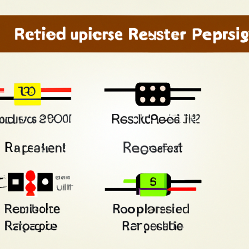
The basic resistor symbol is a simple zigzag line, representing a standard resistor. This symbol is widely recognized and used in most circuit diagrams to indicate a fixed resistor.
B. Variable Resistor Symbols
Variable resistors, which allow for adjustable resistance, have distinct symbols:
1. **Potentiometer**: Represented by a zigzag line with an arrow indicating the adjustable terminal, the potentiometer symbol is used in applications where variable voltage is required.
2. **Rheostat**: Similar to the potentiometer, the rheostat symbol also features a zigzag line but typically has two terminals, indicating its use in current control applications.
C. Special Resistor Symbols
Certain resistors have unique characteristics that necessitate special symbols:
1. **Thermistor**: A thermistor is a temperature-sensitive resistor. Its symbol often includes a curved line to indicate its temperature-dependent behavior.
2. **Photoresistor**: This light-sensitive resistor is represented by a symbol that includes a light source, indicating its response to light levels.
3. **Resistor Networks**: When multiple resistors are connected in a network, a specific symbol is used to represent the entire network, simplifying circuit diagrams.
IV. Standards Governing Resistor Symbols
The standardization of resistor symbols is governed by several key documents:
A. IEC 60617: Graphical Symbols for Diagrams
IEC 60617 is an international standard that provides a comprehensive set of graphical symbols for use in electrical and electronic diagrams. This standard includes symbols for various types of resistors, ensuring consistency across different applications and regions.
B. IEEE Std 91: Standard Graphic Symbols for Electrical and Electronics Diagrams
IEEE Std 91 outlines graphic symbols for electrical and electronics diagrams, including those for resistors. This standard is widely adopted in the United States and serves as a reference for engineers and designers.
C. ANSI Y32.2: Graphic Symbols for Electrical and Electronics Diagrams
ANSI Y32.2 complements the IEC and IEEE standards by providing additional graphic symbols for electrical and electronics diagrams. This standard is particularly relevant for engineers working in the U.S. and ensures that resistor symbols are represented consistently.
V. Importance of Adhering to Standards
Adhering to established standards for resistor symbols is crucial for several reasons:
A. Enhancing Communication Among Engineers
Standardized symbols facilitate clear communication among engineers, reducing the likelihood of misunderstandings and errors in circuit design. When everyone uses the same symbols, it becomes easier to collaborate on projects and share ideas.
B. Reducing Errors in Circuit Design
Using standardized symbols minimizes the risk of errors in circuit design. Engineers can quickly identify components and their functions, leading to more accurate and reliable designs.
C. Facilitating International Collaboration
In an increasingly globalized world, engineers often work on international projects. Standardized symbols ensure that engineers from different countries can understand each other's work, fostering collaboration and innovation.
D. Ensuring Safety and Compliance
Adhering to standards helps ensure that electrical designs meet safety and compliance requirements. This is particularly important in industries where safety is paramount, such as aerospace and medical devices.
VI. Practical Applications of Resistor Symbols
Resistor symbols are used in various practical applications, including:
A. Circuit Diagrams
Circuit diagrams are essential for visualizing electrical systems. Standardized resistor symbols allow engineers to create clear and accurate representations of circuits, making it easier to analyze and troubleshoot designs.
B. Schematic Representations
Schematic representations of circuits often rely on standardized symbols to convey information efficiently. Resistor symbols play a crucial role in these representations, helping engineers understand the relationships between components.
C. PCB Design
In printed circuit board (PCB) design, standardized resistor symbols are used to represent components accurately. This ensures that the final product functions as intended and meets design specifications.
D. Educational Materials
Standardized resistor symbols are also used in educational materials to teach students about electrical engineering concepts. Consistent symbols help students grasp complex ideas more easily.
VII. Challenges in Standardization
Despite the importance of standardization, several challenges persist:
A. Variability in Regional Standards
Different regions may adopt varying standards for resistor symbols, leading to confusion and inconsistency. Engineers working internationally must be aware of these differences to avoid miscommunication.
B. Technological Advancements and New Components
As technology evolves, new components and technologies emerge, necessitating updates to existing standards. Keeping standards current with technological advancements can be a challenge for standardization organizations.
C. Resistance to Change in Established Practices
Established practices can be difficult to change, even when new standards are introduced. Engineers may be resistant to adopting new symbols, preferring to stick with familiar representations.
VIII. Future Trends in Resistor Symbol Standards
Looking ahead, several trends may shape the future of resistor symbol standards:
A. Digitalization and Software Tools
The rise of digital design tools and software is transforming how engineers create and share circuit diagrams. These tools often incorporate standardized symbols, making it easier to adhere to established standards.
B. Integration of Smart Components
As smart components become more prevalent in electrical engineering, new symbols may be needed to represent their unique characteristics. Standardization efforts will need to adapt to these changes.
C. Potential for Global Standardization
There is a growing push for global standardization of electrical symbols, including resistor symbols. This could simplify communication and collaboration among engineers worldwide, fostering innovation and efficiency.
IX. Conclusion
In conclusion, resistor symbols are a vital aspect of electrical engineering, serving as a universal language that enhances communication, reduces errors, and ensures safety. The historical context of these symbols, the governing standards, and the importance of adherence to these standards cannot be overstated. As technology continues to evolve, engineers and educators must remain vigilant in promoting the use of standardized symbols to facilitate collaboration and innovation in the field. By embracing these standards, we can ensure a brighter future for electrical engineering and its practitioners.
X. References
A. List of Standards and Guidelines
- IEC 60617: Graphical Symbols for Diagrams
- IEEE Std 91: Standard Graphic Symbols for Electrical and Electronics Diagrams
- ANSI Y32.2: Graphic Symbols for Electrical and Electronics Diagrams
B. Recommended Reading on Electrical Symbols and Standards
- "Electrical Symbols for Drafting" by David A. Madsen
- "The Art of Electronics" by Paul Horowitz and Winfield Hill
C. Relevant Online Resources and Organizations
- International Electrotechnical Commission (IEC) [www.iec.ch](http://www.iec.ch)
- Institute of Electrical and Electronics Engineers (IEEE) [www.ieee.org](http://www.ieee.org)
- American National Standards Institute (ANSI) [www.ansi.org](http://www.ansi.org)


